Introduction
In a Tech. Brief post in February this year – Building Robust Wireless IP Surveillance Networks – we discussed ways to build a robust wireless IP surveillance network; one that would be resilient in the face of network failure, base station failure, and recorder failure.
This post looks at ways a user can go about building redundancy in Homeland Security implementations.
Disaster Recovery in Homeland Security
In the case of organisations, Disaster Recovery (DR) is a process to ensure the continued functioning of the organisation’s operations, in the event of a significant externally-induced deviation from SOP (Standard Operating Procedure). It is assumed that such deviations are rare.
In the case of Homeland Security, DR needs to be a part of the SOP itself, given the fact that the planner works in an environment where the homeland faces multiple threats. How does one go about doing so, while ensuring that the cost of implementing such a solution does not make it an unviable proposition.
There are five sub-systems that require a degree of redundancy built into their design, in order to ensure a minimum level of DR in the Homeland Security architecture:
| SUB-SYSTEMS | FUNCTION |
|---|---|
| Sensor | Capturing surveillance data |
| Transmission Network | Transmitting surveillance data to recorders |
| Recorder and VMS (Video Management System) | Recording and displaying surveillance data |
| Command & Control Centre | Analysis of surveillance data, and coordination of response |
| Backhaul/Backbone | Making available information outside the local area |
Sensors
 |
|---|
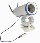
| Wireless Camera |
Traditionally, users have resorted to using only one type of sensor (say, surveillance cameras) for a specific surveillance requirement (say, monitoring human traffic at an airport). In many cases, users may install a mix of surveillance cameras (fixed, PTZ, person-wearable) to ensure a greater level of detail of the entities under surveillance.
In addition, depending on the levels of surveillance and the variety of entities under surveillance, a user may implement a mix of sensors (trace detectors for explosives/contraband, X-ray screeners for baggage, etc.).
Sensor-level redundancy, without setting up a parallel network, can best be implemented using two design features:
| Overlap: | |
| Sensors, of a particular type, are arranged such that each sensor’s surveillance frame overlaps parts of the surveillance frames of its neighbouring sensors. Taking the example of surveillance cameras, using a camera-placement utility, an arrangement of cameras can be created, that allows an area to be covered even when the primary surveillance camera for that frame stops functioning. | |
| Variety: | |
| Different types of sensors can be used for the same type of entity under surveillance. For example, a combination of optical cameras and SCADA sensors can be used to secure an industrial plant. |
 |
|---|
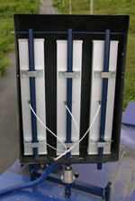
| Antenna Pod |
Transmission Network
The connection from the sensors to the recorders can be wired or wireless. In either case, a disruption to the primary connection should not affect the transmission of surveillance data to the recorder. Disruptions can be a cut cable, in case of a wired sensor, or jammed signals, in the case of a wireless sensor. Redundancy in the transmission network is difficult to design inexpensively (dual connections in the case of wired sensors, wired and wireless connections in the case of wireless sensors, or peer-to-peer wireless connections in the case of wireless sensors); so it may be more efficient using a mix of sensors, each using a different transmission network.
 |
|---|
| VMS Station |
Recorders
The recorder sub-system (DVR or NVR or PC-VR) can be made DR-ready by supporting cold and hot stand-by recorders. This is not a feature supported on all DVRs/NVRs/PC-VRs, and may be offered only with Enterprise-versions of a VMS.
A simpler design would be to implement an archiving policy that back-ups the surveillance data to an off-site facility at regular intervals.
Command & Control Centre (C&CC)
The Command & Control Centre (C&CC) sub-system is the nerve-centre of a Homeland Security operation. Redundancy can be achieved at two levels:
| Hot Stand-by Redundancy: | |
| All key equipment in the C&CC have hot stand-bys, so that in the event of a hardware failure there is no interruption to activities in the centre. | |
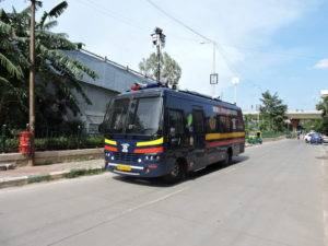
| Mobile Command & Control Centre: | |
| To enable DR-level redundancy, a stand-by C&CC can be set up on a mobile platform which is located away from the fixed C&CC. In case of the fixed C&CC being disabled, the mobile C&CC takes control of all surveillance feed, through a manual switching process. |
 |
|---|
| MC3S |
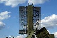
Backhaul/Backbone
The connection from the C&CC to users in other geographies requires a connection to a backhaul network. Usually, a braodband link is configured from the fixed C&CC to the outside world. Redundancy with respect to the backhaul can be achieved through fall-back options such as a broadband wireless backhaul (in the case of fixed/mobile C&CC), satcom (in the case of fixed/mobile C&CC), and leased lines (in the case of fixed C&CC).
Conclusion
Homeland Security users need to consciously plan for and design redundancy in the surveillance solutions they implement at their facilities, if they wish the solutions to function in an emergency
Mistral Solutions offers the Mobile Command & Control Centre, as well as fixed Command &
Control Centre solutions to customers looking at implementing highly redundant Homeland Security solutions. In addition, Mistral offers sensor, recorder, and transmission solutions with various levels of redundancy.