Introduction
Many organisations and entities had opted to go in for wired video surveillance networks for outdoor requirements in the past, even if the environment demanded a wireless network, on account of the unproven nature of wireless networks and the lack of robustness of such networks. Today, however, with field-proven wireless solutions available, many of these organisations and entities have the option of expanding these wired networks with wireless segments.
This brief looks at the implementation approach to setting up a wireless video surveillance infrastructure as a replacement to or as an extension to a wired video surveillance infrastructure. Please note that the point of discussion here is the connection between the cameras and the DVRs/NVRs, and not the backhaul. The subject of wireless backhauls has been covered in an earlier Tech. Brief – April 2010, Wireless Broadband Communications.
Implementation Approach
The decision to transition a surveillance infrastructure to wireless has to be based on an analysis of the location and its characteristics. Use-case information and environment information need to be gathered before decisions can be taken on the technology and devices to be used for the wireless network. The required information relates to the following areas:
Environment:
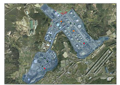
The nature of the environment in which the cameras are to be installed has a bearing on the wireless technology and the specifications of the equipment to be installed. Information such as the quantum of human and vehicular traffic passing the camera sites, the presence of foliage and buildings in the vicinity, and such locational information enables the user to decide whether the camera locations are going to be in LoS (Line-of-Sight), nLoS (Near LoS), or NLoS (Non LoS) of the video server.
- 802.11x in the case of LoS, low-traffic, low-obstruction sites
- 802.11x or OFDM in the case of nLoS, low-traffic, low-obstruction sites
- OFDM in the case of nLoS, medium-traffic, medium-obstruction sites
- COFDM in the case of NLoS sites.
In addition, decisions pertaining to transceiver signal strength (100mW or 500 mW) and antenna gain (7dBi or 9dBi) will depend on the environment.
Ideally, a map of the area needs to be created with the locations of the cameras, and all significant obstructions and traffic densities at and across these locations.
Span:
The distances between the cameras and the video server will help determine the architecture of the wireless network and the type of equipment to be configured at or close to the cameras. Very long distances (over half-a-kilometre) will benefit from OFDM or COFDM technology, while short distances (below a couple of 100 metres) can be covered using 802.11x technology. Minor extensions to distance can be achieved using higher-gain antenna and higher-power transceivers.
An alternative approach is to move from the traditional Point-to-Point (PtP) architecture to a Point-to-MultiPoint (PtMP) architecture. In such a move, an access point is set-up close to a group of cameras and this AP then links to the video server. Several such APs can be configured, depending on the distribution of the cameras.
The map of the location can now be filled in with the distances between the cameras and the video server.
Equipment:
CPE
BTS
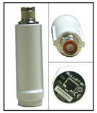
Typically the wired cameras will be fitted with a CPE (Customer Premises Equipment), that connects to the Ethernet port of thecamera (if it is an IP camera) or to the Ethernet port of the encoder (if it is an analogue camera connecting to an IP infrastructure). The CPE is usually a wireless bridge conforming to one of the wireless technologies (802.11x or OFDM or COFDM).
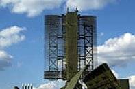
The video server end will be configured with a BTS/BS (Base Transceiver Station/Base Station), with three or four sector antennae. In a PtP architecture, the CPEs will communicate directly with the video server BTS. In case the wireless architecture is PtMP, there will be a BTS (AP) for every in-proximity group of cameras, and this BTS will communicate to the BTS at the video server end.
The type of antenna and the gain of the antenna will be chosen based on the environment and the distances involved.
Implementation Banana-peels
Despite the best planning, there are a couple of potential banana-peels a user could slip on during implementation:
- Link issues:
Issues such as low link quality, high error rate, link congestion, and hidden terminal cause network problems and can result in network instability. Software tools provided by the equipment vendors troubleshoot link issues. In the absence of software tools, a user may need to invest on an RF-meter to measure signal strength at camera installation points. - Clock synchronization:
Sometimes clock drifting among devices on the wireless network can cause issues, on account of the inability of the devices to synchronise for network operations. This is usually not a problem if all the equipment is from a single vendor. - Wi-fi connectivity:
802.11x is not as robust a wireless standard as OFDM and COFDM, so when implementing a Wi-fi network, it would be useful to keep in mind situations and devices that create problems with signal transmission. An earlier Tech. Brief – August 2009, Do’s and Don’ts of Wi-fi Connectivity – covers common implementation issues with 802.11x networks.
Conclusion
Transitioning from wired infrastructure to wireless infrastructure is no longer the headache and risk it used to be. With the sophistication of equipment and troubleshooting tools available in the market, users can confidently plan such transitions as they expand or upgrade their surveillance infrastructure.
Mistral offers several wireless solutions for video surveillance requirements, including native 802.11n support, and support for 802.11n, OFDM, and COFDM over CPEs.